Intersection Test
Shading Polygons.
Copyright (c) Susan Laflin. August 1999.
A polygon is an area enclosed by a sequence of linear segments. There is no restriction on the complexity of the shape produced by these segments, but the last point must always be connected to the first one giving a closed boundary. This differs from Polyline which may produce an open curve with the first and last points being any distance apart. Since a polygon defines an area, then it is possible to decide whether any other point is inside or outside the polygon and there are two very simple tests to determine this.
The GKS Fillarea function has the same parameters as polyline, but will always produce a closed polygon. The filling of this polygon depends on the setting of the appropriate GKS parameter. The FillAreaStyles are hollow, solid, pattern and hatch. The hollow style produces a closed polygon with no filling. Solid fills with a solid colour. Pattern uses whatever patterns are offered by the particular system. Hatch will fill it with lines in one or two directions. Algorithms for hatching and cross-hatching are described in this section.
Intersection Test
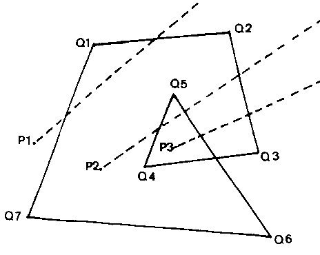
Consider the situation illustrated in the figure below. To determine which of the points Pi, (i=1,2 or 3) lie inside the polygon, it is necessary to draw a line from Pi in some direction and project it beyond the area covered by the polygon. If the number of intersections of the line from Pi with the sides of the polygon is an even number, then the point lies outside the polygon. (Note that the line must start at Pi and may not extend back behind Pi - it is an half-infinite line from Pi). This means that the triangle to the right of the line Q4 Q5 in the figure counts as outside the polygon. If you wished to make it doubly inside, you would have to introduce a parameter equal to the minimum number of intersections of all half-infinite lines through Pi.

Intersection Test
It is then easy to see that the figure gives values of 0, 2 or 4 for lines through P1 with a minimum of 0. For P2, there are values of 1 or 3 with the minimum=1. All lines from P3 have a value 2.
One possible problem arises when lines pass through a vertex. The line P2 Q5 must count the vertex Q5 as two intersections while P2 Q2 must only count Q2 once. The easy way to avoid this problem is to omit all lines which pass through vertices. This still leaves plenty of lines to test the position.
Angle Test
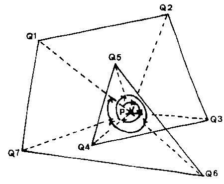
Here the point Pi is joined to all the vertices and the sum of the angles Qk Pi Q(k+1) is calculated. If counter-clockwise angles are positive and clockwise ones are negative, then for a point Pi outside the polygon there will be some positive angles and some negative and the resulting sum will be zero.
For a point Pi inside the polygon, the points will be either all positive or all negative and the sum will have a magnitude of 360 degrees. The next figure illustrates this for the same polygon as figure 3.1the previous figure and a point P inside the triangle (but outside the polygon).
Angle Test
Here the sum of angles is 2 * 360 degrees, thus implying that it is doubly inside the polygon. To give consistency with the Intersection Test, this test must be carefully worded. Having evaluated the sum of angles, it will be n * 360 degrees. If n is an even number, then the point P lies outside the polygon, while if n is an odd number, then P lies inside the polygon.
Once a unique method of deciding whether a point is inside or outside a polygon has been agreed, it then becomes possible to derive algorithms to shade the inside of a polygon. The two main methods here are linear, which is similar to shading the polygon by drawing parallel lines with a crayon, and floodfill, which is similar to starting with a blob of wet paint at some interior point and spreading it out to fill the polygon.
Linear Algorithm for Polygon Shading
Hatching a Triangle
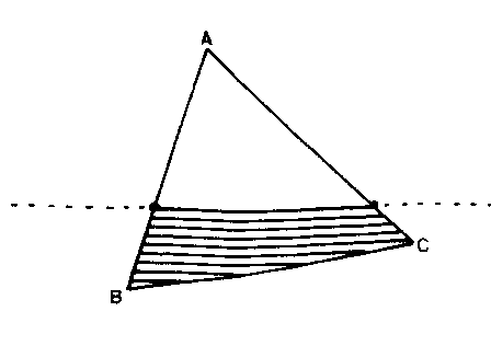
This involves shading the polygon by drawing a series of parallel lines throughout the interior. The lines may be close enough to touch, giving a solid fill or they may be a noticeable distance apart, giving a hatched fill. If you have two sets of hatched lines at right angles to each other, this gives a "cross-hatched" result. The figure shows a triangle in the process of being hatch-filled with horizontal lines. For each horizontal scan-line, the following process must be applied.
1. Assume (or check) that the edge of the screen is outside the polygon.
2. Calculate the intersections Pi of this horizontal line with each edge of the polygon and store the coordinates of these intersections in an array.
3. Sort them into increasing order of one coordinate.
4. Draw the segments of the hatch-line from P1 to P2, P3 to P4 and so on. Do not draw the intervening segments.
5. Repeat this process for each scan-line.
Problems at Vertices
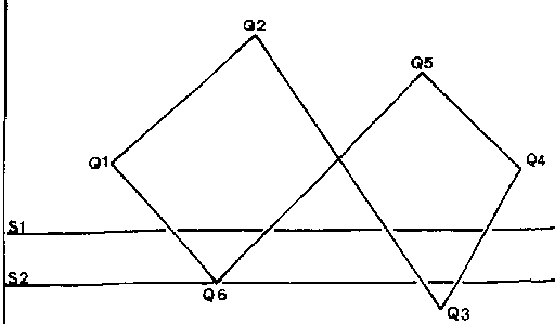
(Note that this does not rely on the lines being horizontal, although scan-lines parallel to one of the axes makes the calculation of the intersection points very much easier). The figure shows one problem with this approach. The scan-line s1 will work correctly since it has four distinct intersections, but the scan-line s2 has two coincident intersection points at the vertex Q6. This is detectable since the number of intersection points will be an odd number.
Looking at the vertices, you can see that moving from Q5 to Q6, y decreases as x decreases and from Q6 to Q1, y increases as x decreases. In this case, the hatch lines have the equation y=constant and so this reversal in the direction of y indicates a vertex which must be included twice and consequently known as a Type 2 vertex. Q1 on the other hand is a Type 1 vertex since y continues to increase when going from Q6 through Q1 to Q2. If the shading uses vertical lines (x = constant) then it is necessary to study the behaviour of x to determine the types of vertex.
If you have an odd number of intersections and only one of them coincides with a vertex, then it is usually safe to assume that this value needs to be included twice. This may save some time in your algorithm, and will shade most polygons successfully. The full method, testing the type of vertex whenever a vertex is included in the intersection list, will successfully shade even the few cases when two Type Two vertices appear in the intersection list thus giving an even number of points and at least one segment incorrectly drawn.
The other problem case occurs when one of the sides of the polygon is parallel to the direction of shading. Mathematically this has an infinite number of intersection points, but computationally only the two end points should be entered in the array so that the whole line is shaded as part of the interior.
Floodfill Algorithm for Polygon Shading
This works in terms of pixels and is applied after the lines forming the boundary have been converted into pixels by a DDA algorithm. The background of the screen has one pixel-value, called "old-value" and the points forming the boundary have another, called "edge-value". The aim of the algorithm is to change all interior pixels from "old-value" to "new-value". (e.g. from black to red) Assume the following software is available:
a) A function Read-Pixel(x,y) which takes device coordinates (x,y) and returns the value of the pixel at this position.
b) A routine Write-Pixel(x,y,p) which sets the new value p to the pixel at the position (x,y) in device coordinates.
Then, starting at the designated seed point, the algorithm, moves out from it in all directions, stopping when an "edge value" is found. Each pixel with value "old value" is changed to "new-value". The recursive method stops when all directions have come to an "edge value".
Because this method is applied to pixels on the screen or in the display buffer, it may run into problems arising from the quantisation into pixels of a mathematical line which is infinitely thin and recorded to the full accuracy of a floating-point number within the computer.
Intersecting Lines
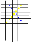
One such problem concerns the method of identifying an intersection of two lines. If you calculate it mathematically, then the equation will give a correct result unless the lines are parallel or nearly parallel. On the other hand, on some hardware it may be quicker to check whether the two lines have any pixels in common and this can be dangerously misleading in some cases. The previous figure shows two lines, one at an angle of 45o and the other at an angle of 135o which cross near the centre of the diagram without having any pixels in common. This type of problem is unlikely to affect the Floodfill routine given above, since the scan-lines move parallel to the x and y axes and the DDA algorithm described earlier ensures that every line has at least one pixel illuminated on each scan-line.
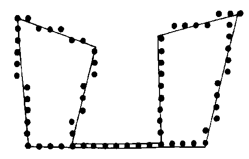
However the next figure illustrates another possible problem. Note that in a complex polygon with sides crossing each other, you will need one seed point in each section of the interior to floodfill the whole area. This also occurs in a polygon as shown in below, even though it does not have any of its sides, indicated by the lines in the figure, crossing each other.
Quantisation of Pixels
Mathematically it is all one contiguous area and any tests on the equations of the sides for intersections will confirm this. However two of the lines are nearly parallel and very close together and consequently although both lines are quite separate and distinct in their mathematical equations, they lead to the same row of pixels after quantisation. The scale of this figure has been enlarged so that the quantisation into pixels appears very coarse in order to emphasize this problem. This polygon will require two seed points in order to shade it completely using the Floodfill algorithm. A little thought will allow you to produce many other similar examples and these can readily be studied by drawing the polygons on squared paper and then marking in the pixel patterns which result.
This approach remains of interest in spite of its problems because some terminals provide a very fast hardware polygon fill from a given seed point. Similarly, some microcomputers provide a function to fill the interior of a triangle. To use this facility, you must first split the polygon into triangles and while this is easy for a convex polygon (one whose internal angles are all less than 180o) it is very much more difficult for the general case where you may have sides crossing each other and holes inside the polygon.